|
RGB |
|
|
This project
is a DICE (DIE) made with 7 LEDs. Normally the LEDs are red or green,
but we have used RGB LEDs to produce an interesting display as well as
creating a number of other effects.
The project is built on Matrix Board with wiring created with fine
enamelled wire and the it comes with a
pre-programmed chip containing a number of different effects.
You can also program the chip yourself and use this project as the
beginning to: "learning to write your own programs."

RGB
LED DICE on
matrix board
The CIRCUIT
The project creates a number of effects on an RGB LED,
including PWM (Pulse Width Modulation) to show the effect of turning on
the LED(s) for a very short period of time then turn the LED(s) off for
a longer period of time. THE RGB LED SURFACE-MOUNT COMPONENTS

Underside of RGB LED
DICE showing SM
components
The PC track is cut just before the 221 SM resistor
and just after the 271 SM resistor (see note below).
Note the link using enamelled wire.
The 47k SM resistors are not needed as the
micro has 47k internal pull-up resistors enabled.
RGB
LED DICE Circuit
The circuit is very simple. It is
just 7 RGB LEDs, 2 switches a piezo diaphragm and 8 other components. All the work is done by the micro.
The diode reduces the 6v supply to 5.4v and also prevents reverse voltage
appearing on the chip.
This will reduce the brightness and also consume less current. When this
is done to all three LEDs a range of colours can be created. This
involves delivering a different percentage of ON-TIME for each LED to
produce a specific colour.
The major purpose for the introduction of the RGB LED was to produce a
wide range of colours, plus white.
This allows it to be used for screens such as TV screens, to reproduce
moving images.
Any sort of display requires a lot of LEDs and this requires many
drive-lines. A single 8-pin micro an only drive one or two LEDs and we
have opted to use a single LED and show the range of effects that can be
produced.
The RGB LED supplied in the kit is high-bright. It is
too bright to look at directly but can be used for all sorts of
applications and effects. You can reduce the brightness by increasing
the value of the current-limiting resistors to suit your own
application. The PWM sequences reduce the brightness and you can observe
how effective they are at reducing the current consumption. We have used
220R and 270R resistors to reduce the brightness so the output is
not too bright.
They also make the project look simpler as they "disappear" under the
board; or if you are developing a single-sided project, they reduce the
size of the final design.
You will need fine tweezers to hold
them in place while one end is soldered.
Always use very fine solder as you only need very little for each
component and the main reason for adding extra solder is to take advantage of
the flux to clean the connection. Always solder resistors with the value
showing.
CONSTRUCTION
The RGB LED Dice
project is built on Matrix Board.
The kit of components comes with all the parts you need to get the
project working, including a pre-programmed chip and PC
board.
The parts are fitted
as shown in the photo above. When all the through-hole components have
been fitted, they are soldered in place and the leads cut off. Then the
surface-mount resistors are added to the underside of the board. In most
cases, one pad will already have solder and the resistor is fitted to
this pad first. Then the other end is soldered. You will have to hold
the resistor with tweezers while soldering the first end. Mae sure the
resistor code can be seen.
|
|
|
TESTING THE CIRCUIT
To assist in testing the
circuit, you may need a Logic probe. The RGB LED Dice circuit is
very simple and the following Logic Probe can be put together in less
than an hour. It will indicate HIGHs and LOWs as well as pulses.
The author did not need the Logic Probe to test the RGB LED Dice project
as the circuit worked the first time it was switched on.
However the circuit was tested by getting a 6v supply with 470R series
resistor and probing the pins of the 8-pin IC socket without the chip
being installed.
As each set of pins was tested, the corresponding colour illuminated to
prove the wiring was correct.
The author makes a point of only using a simply multimeter and a Logic
Probe to test any of the projects in this series because these are the
only pieces of test gear that will be available to the average hobbyist.
So, we have two areas of interest. Construction and Programming and
it's up to you to take it on.
The project is designed for all sorts of uses, including models such as
train layouts, alarms and similar effects.
But the real thing we want to get across, is programming.
This is another example of using a simple 8 pin chip to provide a number
of features that would take many logic chips (such as counters and gates) and lots of components to
duplicate.
It also highlights our method of hand-coding as an effective way to
produce a program.
This project uses about 400 instructions to produce the effects and it uses the EEPROM to store the sequence
produced by the user (sequence 1) - and show it at turn-on.
In this respect, some of the sub-routines in the program are quite complex and suitable
for the advanced programmer. However, if you are a beginner, you can
read through the program and most of the sub-routines will be easy to
follow as each line of code is explained. You have to start somewhere
and this project offers a challenge.
Most projects with a program of this complexity are only available as a
pre-programmed chip or only the hex code is available. There is usually no
attempt at educating the reader in programming.
That's the difference between our projects and all others.
We offer a learning curve.
For every hour of effort you put into reading, building and using one of
our microcontroller projects, you get the experience of 100 hours of
effort that has been put into the design to make it appear simple.
All you have to do is start . . .
|
INSTRUCTIONS FOR USE Press the "Roll Dice" button and the display will flash to give the impression of a rolling dice and will settle on a result. The second button produces a number of effects on the display. There are 5 different effects and each time the button is pressed a different effect will be displayed. |
PROGRAMMING THE
CHIP
The kit comes with a pre-programmed PIC chip but if you want to program
your own chip or modify the program, the .hex file is available as well
as the assembly file, so you can see how the program has been written
and view the comments for each line of code.
The PIC12F629 is one of the smallest micros in the range but you will be
surprised how much can be achieved with such a tiny micro.
The program contains sub-routines to produce delays, sequences on the
display and both read and write EEPROM jobs that require accurate code
- including a special sequence - called a handshaking sequence that
prevents the EEPROM being written due to glitches.
Even a program as simple as this is not easy to put together and to
assist in this area, we have provided a whole raft of support material.
Not only do we provide a number of programs with full documentation but
our approach to programming is simple.
It involves a method of "copy and paste" whereby sub-routines
are taken from previously written code and copied into your program. Any modifications are
made in very small steps so that each can be tested before adding more
code.
This is exactly how we produce a complex project. Each step is written
and tested before adding the next step.
This saves a lot of frustration as it is very easy to add a line
of code that is incorrect and get an unsuspected result.
If you follow our suggestions you will buy a programmer ("burner")
called a PICkit-2 if you are using a laptop. It is the cheapest and best on the market
and comes with
a USB
cable and 2 CD's containing the programs needed to "burn" the chip.
If you are using a desk-top and/or tower with a serial port, you can use
a cheaper programmer called MultiChip Programmer from Talking
Electronics. You
will also need NotePad2 to write your .asm program. This can be
downloaded from Talking Electronics website. You will use
RGB LED Dice.asm
or
RGB LED_Dice-asm.txt as a template for your
program, plus a 6 pin to 5 pin connector that fits between the burner
and the project. This is also available on Talking Electronics website.
As we said before, this project is for medium-to-advanced programmers as
it is very compact and does not have in-circuit programming pins.
To be able to modify the chip you will need a programming socket and
this can be obtained from one of our other projects that contains the 5
pins for in-circuit programming.
You can then put the chip into the other project to be programmed and
modified and re-fit it into this project for execution.
PROGRAMMING LANGUAGE
There are a number of kits, programs and
courses on the market that claim and suggest they teach PIC Programming.
Most of these modules and courses use a PIC microcontroller as the chip carrying out
the processes, but the actual programming is done by a proprietary
language invented by the designer of the course.
Although these courses are wonderful to get you into "Programming
Microcontrollers" they do not use any of the terms or codes that apply
to the PIC microcontroller family.
All our projects use the 33 instructions that come with the PIC
Microcontroller and these are very easy to learn.
We use the full capability of the micro and our pre-programmed chip is
less than the cost of doing it any other way.
In addition, anything designed via our method can be instantly
transferred to a PIC die and mass produced. And we use all the input
pins and all the memory of the chip. The other approaches
use less than 25% of the capability of the memory and one of the pins is not available.
In fact it would be difficult to reproduce this project via any of the opposition
methods. It would require a larger chip and more expense.
You can use our method or the opposition. Just be aware that the two are
not interchangeable.
Ours is classified as the lowest "form" (level) of programming - commonly called
machine code - invented in the early days of microprocessors - and now
called mnemonic programming as each line of code is made up of
letters of a set of words. The opposition uses a higher level language
where one instruction can carry out an operation similar to a
sub-routine.
But you have to learn the "higher level language" in order to create a
program. And this requires a fair amount of skill and capability.
It sounds great and it is a good idea. But if you want to learn PIC
programming, it does not assist you. It is "a step removed" from
learning PIC language. The other disadvantage of the opposition is the
"overhead." The 1,000 spaces allocated for your program is filled with
pre-written sub-routines. You may require only 10 of these sub-routines but ALL
of them are loaded in the memory space. And they take up all the memory.
You have no room for your own program.
To get around this the opposition uses the 128 bytes in EEPROM to deliver
instructions on how to apply the sub-routines. This provides about 30 powerful instructions using their
language called BASIC (or a similar language).
It's a bit like selling a diary filled with all the paragraphs you need
to express yourself, and leaving a few blank pages at the back for you
to write single lines such as: see page 24, paragraph 7, see page 63
paragraph 4, to create your diary entries.
It depends on how much you want to be in charge of writing a program. Using
our method is like writing your own auto-biography. Using the opposition
is like getting a "ghost writer."
When using a higher level language to create a program, you have absolutely no
idea how the code is generated for the micro.
In some of the developmental kits, the code is "locked away" and you are
NEVER able to access it.
Everything runs smoothly until a fault appears. With our method you can
see the code. With the other methods, you cannot see the code - it's
like doing key-hole surgery without the advantage of an
illuminated endoscope to see what you are doing.
Everything has its place and our method of hand-assembly is only
suitable for very small micros and you will eventually need to "learn a
high level language." The PIC12F629 has over 1,000 locations for code
and this equates to more than 20 pages when printed, so this is about
the limit to doing things by hand.
But our drive is to show how much can be done with the simplest devices
on the market, at the lowest cost.
Anyone can show you high-technology at a high price but this is not
where you start and this is not where you get enthusiasm.
We provide the things to get you started. That's the difference.
CHARLIE-PLEXING
MODIFYING THE PROGRAM
The
PROGRAM
HISTORY
When ever you invent a
product or idea, GIVE IT A NAME.
That's the first thing I do when I produce a new project.
It gives you a "point of reference."
And that's what has been done by the inventor of the circuit we have
used in this project.
It's called CHARLIE-PLEXING and
is basically the concept of
connecting as many LEDs as possible to the outputs of a micro.
Each output of a micro can deliver current (25mA) when it it HIGH and
sink 25mA when it is LOW.
This means it will illuminate a LED when two outputs are in particular
directions and another LED when the outputs are reversed.
With 3 outputs, 6 LEDs can be illuminated, but not all at the same time.
With 4 outputs, 12 LEDs can be connected and sometimes more than one LED
can be illuminated at the same time.
With our RGB LED Dice project, two LEDs are connected in parallel
(called Display LED "A" and "A+"), two
more LEDs are connected in parallel (called Display LED "B" and "B+") and two more LEDs are connected in
parallel (called Display LED "C" and "C+"). 9 leads are produced from these 6 LEDs.
The final LED (the centre LED of the display ("D") has 3 more leads. Thus we
have a total of 12 leads and by charlieplexing we can illuminate any of
the colours from any of the LEDs. We have already mentioned that
all the LEDs cannot be turned on at the same time, however sometimes
more than one colour can be turned on at the same time and this will be
discussed later.
We now come to another interesting feature.
The maximum current from each output of the micro is 25mA.
If you drive any of the colours of the RGB LEDs with 25mA,
the light output will be blinding. The LEDs will be far too bright to
view and the colours will be blurred.
We have a choice. We can drive them with 12mA or put 25mA through them
for 50% of the time. You would think this comes to the same brightness.
But no so.
Our eyes are non-linear and by delivering 25mA for 50% of the time,
produces a brightness almost equal to the full 25mA - so it is a much
more effective way of illuminating the display.
In fact we can reduce the time to about 10% and still produce a viewable
brightness. The reason is the LED comes on at full brightness @ 10% of
the time and our eyes see this peak and retain the brightness until the
next peak arrives. If we pulse the LED very quickly, the LED will appear
to be bright ALL THE TIME.
We need to employ this trick because we cannot turn on all the LEDs at
the same time. Depending on the LEDs we want to illuminate or the
effects we want to show, we may have up to 8 different colours being
illuminated, one after another.
All the complexities of how the colours are turned on has been worked out
and each number, from 1 - 6 has been placed in a separate sub-routine.
All you have to do is call the sub-routine and the appropriate colour
and particular set of "pips" on the display will be illuminated..
And the same applies to the effects. These are worked out separately and
placed in sub-routines.
There is only one simple rule to remember.
To turn on a colour in an RGB LED, one output has to be HIGH and the
corresponding output has to be LOW.
No other LEDs on these two outputs can be illuminated. However LEDs on
the other two outputs can be activated and if this can be done at the
same time, the display will be slightly brighter if it reduces the size
of the "run." This is the number of individual "illuminations" required
to produce an effect.
Very good brightness
can be achieved with a "run-of'-four" as the LEDs are high-bright.
You will notice that some of the unused colours inside the LEDs are connected to the
outputs we are driving and to prevent these
LEDs illuminating, the unused outputs are turned into INPUTS. This means
the line is neither high or low and is equivalent to the LED being
disconnected from that particular line.
The outputs can be changed to inputs at any time during the running of
the program and this gives us great flexibility with driving the
LEDs.
It is quite easy to work out which lines have to be made HIGH or LOW or
turned into an INPUT. Simply look at the circuit.
To modify the program you will need a PICkit-2 programmer and this comes
with 2 CD's containing all the software needed for In-Circuit
Programming.
You will also need a lead (comes with PICkit-2) to connect the programmer to your lap top via
the USB port and an adapter we call 6pin to 5 pin
Adapter to connect
the PICkit-2 to your project. 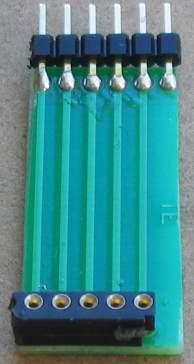
6pin to 5pin
Adapter
Adapter connected for In-Circuit Programming
(the chip is placed in another project for in-circuit
programming
or any PC board with 5 In-circuit Programming pins)
The program looks complex
because the LEDs are being accessed individually and each illumination
requires a separate sub-routine. Two LEDs marked "A" are in parallel,
two LEDs marked "B" are in parallel and two LEDs marked "C" are in
parallel. LED "D" is a single LED. This means the display is
limited to driving and illuminating these pairs of LEDs and you cannot
produce random effects on the display without taking these limitations
into account.
The program
does a bit of
detecting when turned on. It detects to see if a bit has been set in
EEPROM to tell the micro to go to a required sequence or start with
sequence 1.
It also detects if switch A or C has been pressed at the instant the
project is turned on so that the micro is directed to the sub-routine
where the user-sequence can be entered or if the EEPROM bit is to be
cancelled.
All this gets done in the SetUp routine and then the micro goes to Main.
In Main, the program increments a "jump" file and calls a table where it
finds a directive to go to a particular sub-routine.
The sub-routine is executed and the micro goes back to Main where it
looks for a release of SwA. This forms part of a key debounce as the key
must be fully debounced as it is advancing the micro through the
sequences.
To provide a totally reliable debounce, the key is detected as not being
pushed for the duration of a whole cycle of a sequence and a separate loop is then executed where the key can be
detected as being pushed, to advance the program to the next sequence.
To create your own sequence as sequence1, the project is turned off and
SwA pressed while turning the project ON.
This sends the micro to a sub-routine called Attract.
As soon as SwA is released, the program starts to time the duration when
a switch is not pressed and it "times-out" after 2.5 seconds.
The program also times the duration when a LED is illuminated. It also
accepts 2 or 3 LEDs illuminated at the same time. These are all clever
instructions that need to be looked at to see how they operate.
Up to 15 steps can be entered and each step occupies three bytes. The
first value identifies the illuminated LEDs, the second byte identifies
the ON duration (in increments of 5mS) and the third byte identifies the
OFF time.
These 45 bytes are contained in files 30h to 5Fh.
When a switch is not pressed for 2.5 seconds, the program "times out"
and sends the values to the EEPROM. It then shows the sequence on the
LEDs.
If the project is turned off and on again, this sequence will be
displayed as sequence1.
To replace the sequence with something else, simply repeat the steps above.
If you want one of the pre-programmed sequences to appear each time the
project is turned on, simply advance through the sequences by
pressing SwA and when the desired sequence is playing, push SwB.
This will record your choice. Turn the project OFF then ON again and the
chosen sequence will be displayed.
To remove this feature, press SwC when the project is off and at the
same time, turn the
project ON.
All these feature have been added to the program, one at a time, and it
is important to add them in the correct order. For instance, you can only add a removal feature after the
initial feature has been produced. Reading and writing to the EEPROM is
a most complex operation and the instructions must be laid out as shown
in the program, as they include a hand-shaking sequence. When you need this
code it is copied and
pasted in its entirety, to prevent a mistake.
Nearly every instruction has a comment to explain not only what it does, but why it was chosen.
To illuminate each set of LEDs, the
in-out resister (TRIS) must be loaded and the out lines must be taken
HIGH or LOW. Any line configured as an input is effectively removed from
the circuit and does not have any effect.
The first thing to do is create a sub-routine to drive each of the LEDs:
"A," "B," "C," and "D."
The produce a sub-routine that uses 1, 2 or 3 of the previous
sub-routines.
We have already mentioned the fact that the LEDs are too bright when
driven at 25mA and to reduce the brightness, a short delay much be
included.
As you increase the number of sub-routines, you will notice that
previous routines can be used and this saves a lot of space.
Programming is like owning a LEGO factory. As you introduce new
products, you can use many of the previously developed Lego blocks and
bricks.
Here are the files you will need:
RGB LED Dice.asm
RGB LED_Dice-asm.txt
RGB LED Dice.hex
;RGB LED DICE.asm
;****************************************************
;RGB LED FX.asm                                     *
;25 sequences to demonstrate the possibilities for  *
;an RGB LED                                         *
;22-5-2011                                          *
;****************************************************
;			2100h

	END
LED Dice projects have been
around for a long while.
The simplest circuit uses 6 LEDs and they get scanned by a CD 4017 chip.
This is not very impressive.
The next circuit uses a very interesting feature of the 4017 chip. The
"carry out" (pin 12) is HIGH for the first 5 clock pulses.
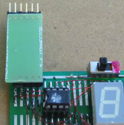
The following circuit uses a PIC12F629 to drive a 7-segment display. It
has the "slow down" feature.
The first output is pin 3, so that just pin 12 is HIGH and thus LEDs "B"
illuminate to produce "2" on the display.
The next output to go HIGH is pin 2 and this makes LEDs B and A
illuminate to produce "3" on the display. Using pin12 reduces the
complexity of the project while producing the "pips" on a dice.
This circuit shows the importance of reading a datasheet thoroughly and
understanding what is going on with the outputs of a chip. The circuit
does not have the "slow down" feature.

The next project uses a PICAXE-08 chip that is really a PIC12F629 but you do
not use any of the PIC instructions to create a program. You use
instructions created by the supplier of the chip and you are effectively
learning nothing about programming a PIC chip. The chip could be an Atmel or NEC or Philips microcontroller.
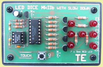
Here are 4 more LED Dice projects: 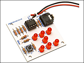


The
first photo shows a project using an oscillator chip and 4017.
The second photo uses a 555 a 4071 OR-gate and a 4017 counter. The
circuit is below. A few diodes can take the place of the 4071 chip
and the project is over-designed.
The third photo shows a microcontroller project using an Atmel
micro. The fourth photo shows a multivibrator made from 2
transistors and a 4017 chip.


